Tuesday, December 24, 2013
Browse »
home»
controller
»
light
»
traffic
»
Traffic Light Controller

Traffic Light Controller
Here the simple traffic light controller which is could be used to educate kids rudiments of traffic light guidelines. The circuit utilizes easily available electronic parts. It generally consists of rectifier diodes (1N4001), a 5V regulator 7805, two timers circuit using IC 555, two relays (5V, single-changeover), three 15W, 230V light bulbs and also several discrete parts.
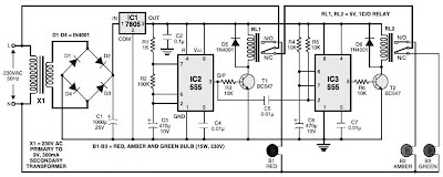
Traffic Light Controller Circuit diagram :
Mains electrical power is stepped down by transformer X1 to provide a secondary output voltage of 9V, 300 mA – AC. Then the transformer output current is rectified by a full-wave bridge rectifier composed of diodes D1 through D4, filtered by capacitor C1 and also regulated by IC 7805 (IC1).
IC2 is wired as a multivibrator with ‘on’ and ‘off’ periods of about 30 seconds each with the part values determined. Once mains power switch is turned on, pin 3 of IC2 goes high for 30 seconds. This, in turn, energises relay RL1 via transistor T1 and the red bulb (B1) glows through its normally-open (N/O) contact. At the same time, mains power is turned off from the pole of relay RL2. As the ‘on’ time of IC2 ends, a triggers IC3 through C5. IC3 is set up as a monostable with ‘on’ time of about 4 seconds, which indicates pin 3 of IC3 will stay high for this period of time and energise relay RL2 through driver transistor T2. The amber bulb (B2) thus lightings up for 4 seconds.
Immediately after 4-second time period of timer IC3 at pin 3 lapses, relay RL2 de-energises and also the green bulb (B3) lights up for the rest of ‘off’ period of IC2, which is about 26 seconds. The green bulb is turned on through the normally closed (N/C) contacts of relay RL2. So when mains electrical switch is turned on, red light will light up for 30 seconds, amber for 4 seconds and green for 26 seconds.
You can easily build this circuit on a general purpose PCB and enclose in a protected box. The box needs to have sufficient area for installing transformer X1 and also two relays. It could be installed near 230V AC, 50Hz power supply or mounted on the PVC tube applied in assembly of the traffic light box.
Design of the traffic light container box is demonstrated in following image:
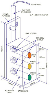
A stout cardboard box of 30x15x10cm3 is needed for housing the lights. To make certain durability, work with a 10x45cm2 plywood plate having 1.5 centimeters thickness and also secure onto it three light outlets and the box utilizing nuts and bolts or screws. Make three tubes of thin aluminium sheet, which is easily offered in equipment stores. The inner diameter of aluminium tubes ought to be such that these can well match on the light outlets. Working with a sharp knife, make holes opposite the outlets carefully. Wire the outlets at the back and take the cables out through the PVC tube.
To begin with, fix three 15W light bulbs (B1 through B3) and then press on the tubes. Support the other ends of the tubes in the holes made on the front panel of cardboard box. Sandwich gelatine papers of the three colors in between two sheets of cardboard and fix over the tubes. The visibility of red, amber and also green lights enhances with their installation on the tubular shape.
Subscribe to:
Post Comments (Atom)
No comments:
Post a Comment
Note: Only a member of this blog may post a comment.