Thursday, December 26, 2013
Browse »
home»
12v
»
30
»
based
»
driver
»
for
»
ldr
»
led
»
leds
»
to
»
up
»
white
»
LDR Based 12V White LED Driver for up to 30 LEDs
While we have now published quite a few LED driver circuits, to date we have not published a design to drive a bunch of high-brightness white LEDs. Such a circuit is now quite desirable as the price of white LEDs has fallen and you can have a handful for not a lot of dollars. However, white LEDs do present a problem because they need a higher drive voltage than monochromatic types such as red, green, orange etc.
Instead of around 1.8V to 2V or thereabouts, they normally require more than 3V to produce their rated brightness. In fact, if you are driving a bunch of them you need to drive them all at constant current otherwise their individual brightness tends to vary markedly. However, if you only have a 12V supply available, you can only put two or maybe three LEDs in series together with a constant current source and this leads to poor efficiency.

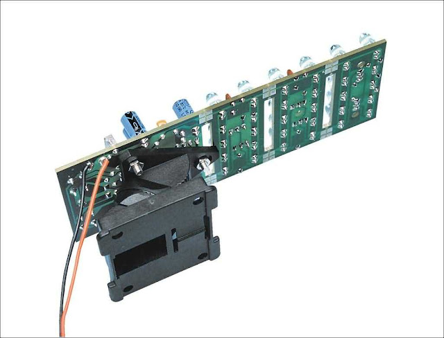
The approach in this circuit is to boost the 12V supply to something around 21V and this means that we can have groups of five LEDs, each in series with their own current source transistors. The result is a single PC board with the drive circuitry and 30 white LEDs. It can be used for lighting in caravans and recreational vehicles, emergency lighting or whatever application you can think of. Current drain is around 190mA at 12V.
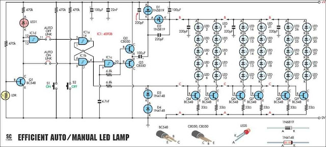
Now let’s have a look at the circuit of Fig.1. It uses just one IC (a 4093 quad NAND Schmitt trigger gate package), a few transistors and diodes, 30 white LEDs and not much else. So where is the familiar boost converter circuit? Answer: there isn’t one or least not one with an inductor switched by a Mosfet. Instead, there is a charge pump inverter, comprising IC1c, transistors Q2 & Q3, Schottky diodes D1 & D2 and a few capacitors. It works as follows:

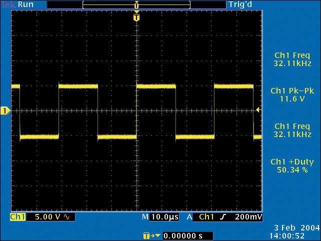
IC1c is connected as an inverter oscillator and its running frequency of about 30kHz is determined mainly by the 6.8kΩ resistor between pins 8 & 10 together with the 4.7nF capacitor at pin 8. This produces a rectangular waveform (not quite square but pretty close) at pin 10 to drive complementary switching transistors Q2 & Q3.
The waveform at their commoned emitters drives a diode pump consisting of two 100μF capacitors and Schottky diodes D1 & D2. The waveform generated by the circuit can be seen in the scope photo of Fig.2.
Oscillator IC1c is controlled by an RS (Reset/Set) flipflop comprising the two NAND gates IC1a & IC1b and this is controlled by pushbutton switches S1 and S2. Normally, this has its pin 4 low and pins 1 & 6 are pulled high via 470kΩ resistors. Momentarily closing S1 (ON) pulls pin 6 low, causing the flipflop to change state so that pin 4 now goes high to enable IC1c which now oscillates at 30kHz.

The 30kHz waveform produced by transistors Q2 & Q3 drives the diode pump referred to earlier and this develops about 21V to drive the LED columns. Each column of five white LEDs is driven by its own current source transistor which has a 33Ω emitter resistor. The bases of all six current source transistors (Q4-Q9) are driven from pin 4 of IC1b via a 6.8kΩ resistor and clamped to a maximum of +1.2V by diodes D3 & D4.
Subtract the 0.6V between the base and emitter of each transistor and you are left with 0.6V across each 33Ω resistor, thus setting the LED drive current to 18mA. Switching the circuit off is accomplished by pushing the OFF switch, S2. This momentarily pulls pin 1 low to toggle the RS flipflop, thus causing pin 4 to go low. This disables IC1c, Q2 & Q3 and also turns off the current source transistors.
Note that there is an interesting wrinkle to this drive circuit, because there is no On/Off switch. This means that the current source transistors must be turned off otherwise they would continue to draw current from the 12V supply even when the circuit is nominally off. The current path may not be obvious but it is via the boost circuit’s diodes, D1 & D2.
As well as using the pushbutton switches S1 & S2 to turn the circuit on and off, there is also a facility to automatically turn the circuit on and off depending on ambient light levels. Links L1 & L2 can be used to provide Auto On and Auto Off respectively and these features can be used separately or together.

An LDR (light dependent resistor) is used to monitor the ambient light level. When light falls upon it, it pulls the base of Q1 low, causing pins 12 & 11 of IC1d to go low and its pin 11 to go high. When darkness falls (or the room lights go out), the process is reversed. Depending on whether you have one or both links connected, you can use the pushbuttons to turn the circuit on and off and have it turn on and/off automatically as well.
Q1 also drives a red high brightness LED (LED1) at very low current, via a 470kΩ resistor. This is a bit of a gimmick but it does have the benefit of showing that this part of the circuit is working, if you have to trouble-shoot it.
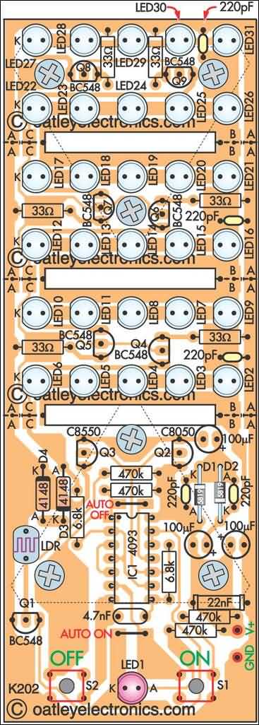
Pins 1 & 2, 5 & 6 and 8 & 9 of IC1 on the circuit are all swapped. The PC board overlay diagram is correct.
LDR Based 12V White LED Driver for up to 30 LEDs
 |
| 30 White LEDs Driver Circuit Diagram |
Instead of around 1.8V to 2V or thereabouts, they normally require more than 3V to produce their rated brightness. In fact, if you are driving a bunch of them you need to drive them all at constant current otherwise their individual brightness tends to vary markedly. However, if you only have a 12V supply available, you can only put two or maybe three LEDs in series together with a constant current source and this leads to poor efficiency.

The approach in this circuit is to boost the 12V supply to something around 21V and this means that we can have groups of five LEDs, each in series with their own current source transistors. The result is a single PC board with the drive circuitry and 30 white LEDs. It can be used for lighting in caravans and recreational vehicles, emergency lighting or whatever application you can think of. Current drain is around 190mA at 12V.
Circuit description
Now let’s have a look at the circuit of Fig.1. It uses just one IC (a 4093 quad NAND Schmitt trigger gate package), a few transistors and diodes, 30 white LEDs and not much else. So where is the familiar boost converter circuit? Answer: there isn’t one or least not one with an inductor switched by a Mosfet. Instead, there is a charge pump inverter, comprising IC1c, transistors Q2 & Q3, Schottky diodes D1 & D2 and a few capacitors. It works as follows:

IC1c is connected as an inverter oscillator and its running frequency of about 30kHz is determined mainly by the 6.8kΩ resistor between pins 8 & 10 together with the 4.7nF capacitor at pin 8. This produces a rectangular waveform (not quite square but pretty close) at pin 10 to drive complementary switching transistors Q2 & Q3.
The waveform at their commoned emitters drives a diode pump consisting of two 100μF capacitors and Schottky diodes D1 & D2. The waveform generated by the circuit can be seen in the scope photo of Fig.2.
RS flipflop
Oscillator IC1c is controlled by an RS (Reset/Set) flipflop comprising the two NAND gates IC1a & IC1b and this is controlled by pushbutton switches S1 and S2. Normally, this has its pin 4 low and pins 1 & 6 are pulled high via 470kΩ resistors. Momentarily closing S1 (ON) pulls pin 6 low, causing the flipflop to change state so that pin 4 now goes high to enable IC1c which now oscillates at 30kHz.

The 30kHz waveform produced by transistors Q2 & Q3 drives the diode pump referred to earlier and this develops about 21V to drive the LED columns. Each column of five white LEDs is driven by its own current source transistor which has a 33Ω emitter resistor. The bases of all six current source transistors (Q4-Q9) are driven from pin 4 of IC1b via a 6.8kΩ resistor and clamped to a maximum of +1.2V by diodes D3 & D4.
Subtract the 0.6V between the base and emitter of each transistor and you are left with 0.6V across each 33Ω resistor, thus setting the LED drive current to 18mA. Switching the circuit off is accomplished by pushing the OFF switch, S2. This momentarily pulls pin 1 low to toggle the RS flipflop, thus causing pin 4 to go low. This disables IC1c, Q2 & Q3 and also turns off the current source transistors.
Note that there is an interesting wrinkle to this drive circuit, because there is no On/Off switch. This means that the current source transistors must be turned off otherwise they would continue to draw current from the 12V supply even when the circuit is nominally off. The current path may not be obvious but it is via the boost circuit’s diodes, D1 & D2.
Auto on/off
As well as using the pushbutton switches S1 & S2 to turn the circuit on and off, there is also a facility to automatically turn the circuit on and off depending on ambient light levels. Links L1 & L2 can be used to provide Auto On and Auto Off respectively and these features can be used separately or together.

An LDR (light dependent resistor) is used to monitor the ambient light level. When light falls upon it, it pulls the base of Q1 low, causing pins 12 & 11 of IC1d to go low and its pin 11 to go high. When darkness falls (or the room lights go out), the process is reversed. Depending on whether you have one or both links connected, you can use the pushbuttons to turn the circuit on and off and have it turn on and/off automatically as well.
Q1 also drives a red high brightness LED (LED1) at very low current, via a 470kΩ resistor. This is a bit of a gimmick but it does have the benefit of showing that this part of the circuit is working, if you have to trouble-shoot it.
Note:
Pins 1 & 2, 5 & 6 and 8 & 9 of IC1 on the circuit are all swapped. The PC board overlay diagram is correct.
- Source
- SiliconChip Online
Subscribe to:
Post Comments (Atom)
No comments:
Post a Comment
Note: Only a member of this blog may post a comment.