Friday, May 31, 2013
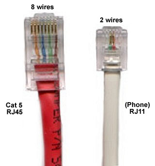
Rj14 Rj11 Pinouts

Telephone Wiring Full Screenshot Telephone Wiring Demo.

Telecom Tips Wiring Your Home For Voip Service O Reilly Emerging.

Rj 11 4 Pair Phone Wiring Color Codes And Diagram Circuit Schematic.

Rj11 Wiring.

Uk Telephone Wiring.
Cat 5 Wiring.

Build An X 10 Status Display The Statx10.
Rj 11 Definition Of Rj 11 In The Free Online Encyclopedia.

Rj14 And Rj11 Pinouts.
Cable Modem With Either Airport Extreme Or Time Capsule Macrumors.
Free Download Gibson Wiring Diagram Schematiccircuit
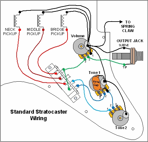
Basic Electric Guitar Circuits Part 3 Workbenchfun Com.

Stratocaster Guitar Set Up Wiring Diagram Gif.

Here Is A Wiring Diagram Of My Electric Guitar That Shows All Wires.

Humbuckers With 5 Way Switching Guitar Wiring Circuit Schematic.

Diagram Showing The Wiring Of A Gibson Les Paul Electric Guitar.

How To Wiring Gibson Les Paul Guitar Schematic Diagram How To Tips.

Free Download Of Gibson Wiring Diagram And Schematic Circuit.

Here Are Some Diagrams Of Electric Guitar Wiring.

Rhythmic Gymnastics Photos Guitar Wiring Diagram.
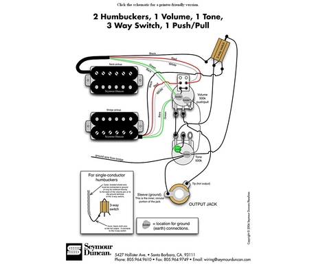
Coil Splitting Seymour Duncan Wiring Diagram 460 100 460 70 Jpg.
Bosch Alternatorinternal Circuits
Jam S Tiger Avon Wiring A Nippon Denso Alternator.

Alternator Wiring Diagram 1978 80 Vehicles.

Chevy Truck Under Hood Wiring Diagram.

About Honda Cb400 And Cb450 Wiring Diagram And Schematics Here.

Garden Tractor Wiring Diagram Parts List Manual Parts Book.

Lexus Sc400 Charging Circuit And Wiring Diagram Circuit Schematic.

Hilux Pickup Power Window Control System Connectors And Wiring Diagram.
Alternator Wiring Diagrams 1g 2g And 3g.

1997 Chevrolet Malibu Wiring Diagram And Electrical System Circuit.
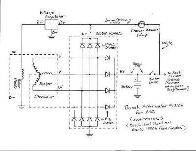
Of This Bosch Alternator S Internal Circuits Is Given Below.
Wednesday, May 29, 2013
2SC5200 and 2SA1943 high fidelity power transistor

Here are two transistors manufactured by Toshiba. 2SC5200 and 2SA1943 transistor pair has been widely applied or used in the amplifier power amplifier because the transistor has a large power, and also not too expensive than other large power transistors. This transistor has the advantage of High breakdown voltage: VCEO = 230 V (min), Suitable for use in 100-W high fidelity audio amplifiers output stage. For more information, please see datasheet below.
Maximum Ratings (Tc = 25°C)


Tuesday, May 28, 2013
12V Flashing Lamp Circuit Diagram
This is good news for vehical lovers.This is 12V Flashing lamp circuit.Yuo can use this circuit for your vehical.Here I have used IC LM317T.
 Note
Note
# Build this on a PCB
# This circuit operates with 12V power supply.
Continue Reading[..]
Note# Build this on a PCB
# This circuit operates with 12V power supply.
Monday, May 27, 2013
Home Smart Cabling Integrate Cabling Existing Home

The Figure Shows The Ring System Of Electric Wiring Wiring Starts.

Solar Powered House Wiring.

Slim Films House Illustrations.

House Wiring Dsl By Kissel.

Electrical Wiring In The Home Existing Nutone 665rsp Wiring.

Home Wiring Video Distribution Catv Tv Dbs.

House Plans And Home Designs Free Blog Archive Home Wiring.

Italy Rome Weather Density Of 40 Sodium Hydroxide Solution.

Home Wiring Video Distribution Catv.

New Home For Smart Cabling Or Integrate Cabling In Your Existing Home.
Sunday, May 26, 2013
Motor Starting
The worked example here is a very simple power system with two voltage levels and supplied by a single generator. While unrealistic, it does manage to demonstrate the key concepts pertaining to motor starting calculations.
Step 1: Construct System Model and Collect Equipment Parameters
 |
| Simplified system model for motor starting example |
The power system has two voltage levels, 11kV and 415V, and is fed via a single 4MVA generator (G1). The 11kV bus has a standing load of 950kVA (S1) and we want to model the effects of starting a 250kW motor (M1). There is a standing load of 600kVA at 415V (S2), supplied by a 1.6MVA transformer (TX1). The equipment and cable parameters are as follows:
| Equipment | Parameters |
|---|---|
| Generator G1 |
|
| Generator Cable C1 |
|
| 11kV Standing Load S1 |
|
| Motor M1 |
|
| Motor Cable C2 |
|
| Transformer TX1 |
|
| Transformer Cable C3 |
|
| 415V Standing Load S2 |
|
 = 4,000 kVA
  = 11,000 V
  = 0.33 pu
  = 0.85 pu
  = 950 kVA
  = 11,000 V
  = 250 kW
  = 11,000 V
  = 106.7 A
  = 6.5 pu
  = 0.85 pu
  = 0.30 pu
  = 1,600 kVA
  = 11,000 V
  = 415 V
  = 0.06 pu
  = 12,700 W
  = 0%
= 0%  = 600 kVA
  = 415 V
 Step 2: Calculate Equipment Impedances
Using the patameters above and the equations outlined earlier in the methodology, the following impedances were calculated:
| Equipment | Resistance (Ω) | Reactance (Ω) |
|---|---|---|
| Generator G1 | 0.65462 | 9.35457 |
| Generator Cable C1 | 0.00261 | 0.00413 |
| 11kV Standing Load S1 | 106.98947 | 69.10837 |
| Motor M1 | 16.77752 | 61.02812 |
| Motor Cable C2 | 0.1002 | 0.01725 |
| Transformer TX1 (Primary Side) | 0.60027 | 4.49762 |
| Transformer Cable C3 | 0.01176 | 0.00576 |
| 415V Standing Load S2 | 0.22963 | 0.17223 |
Step 3: Referring Impedances
11kV will be used as the reference voltage. The only impedance that needs to be referred to this reference voltage is the 415V Standing Load (S2). Knowing that the transformer is set at principal tap, we can calculate the winding ratio and apply it to refer the 415V Standing Load impedance to the 11kV side:

The resistance and reactance of the standing load referred to the 11kV side is now, R = 161.33333 Ω and X = 121.00 Ω.
Step 4: Construct the Equivalent Circuit
 |
| Equivalent circuit for motor starting example |
The equivalent circuit for the system is shown in the figure to the right. The "Near" Thevenin equivalent circuit is also shown, and we now calculate the equivalent load impedance  in the steady-state condition (i.e. without the motor and motor cable impedances included):
in the steady-state condition (i.e. without the motor and motor cable impedances included): ![Z_{eq} = Z_{C1} + left[ Z_{S1} || left( Z_{C3} + Z_{TX1} + Z_{S2}
<br />ight)
<br />ight] ,](http://www.openelectrical.org/wiki/images/math/0/2/a/02a1a0c80a9e161555a63340702617b1.png)

Similarly the equivalent load impedance during motor starting (with the motor impedances included) can be calculated as as follows:
![Z_{eq,s} = Z_{C1} + left[ Z_{S1} || left( Z_{C3} + Z_{TX1} + Z_{S2}
<br />ight) || Z_{C2} + Z_{M1}
<br />ight] ,](http://www.openelectrical.org/wiki/images/math/e/d/a/eda9fc1ebb5ad676599889174e4ce722.png)

Step 5: Calculate the Initial Source EMF
 |
| "Near" Thevenin equivalent circuit for motor starting example |
Assuming that there is nominal voltage at the 11kV bus in the steady-state condition, the initial generator emf can be calculated by voltage divider:
-

-
 Vac
Vac
-
Step 6: Calculate System Voltages During Motor Start
Now we can calculate the transient effects of motor starting on the system voltages. Firstly, the current supplied by the generator during motor start is calculated:


Next, the voltage at the 11kV bus can be found:
-

-
 Vac (or 87.98% of nominal voltage)
-
The voltage at the motor terminals can then be found by voltage divider:
-

-
 Vac (or 87.92% of nominal voltage)
-
The voltage at the low voltage bus is:
-

-
 Vac, then referred to the LV side = 359.39Vac (or 86.60% of nominal voltage)
-
Any other voltages of interest on the system can be determined using the same methods as above.
Suppose that our maximum voltage drop at the motor terminals is 15%. From above, we have found that the voltage drop is 12.08% at the motor terminals. This is a slightly marginal result and it may be prudent to simulate the system in a software package to confirm the results.
Subscribe to:
Posts (Atom)